
Transient VRM Response From a Large Circular Loop Over a Conductive and Magnetically Viscous Half-Space
Abstract
To effectively characterize the impact of viscous remanent magnetization (VRM) on the transient electromagnetic response, we present a set of analytical expressions for the vertical and radial VRM responses generated by a large circular loop over a magnetically viscous half-space. For a step-off excitation, Nel relaxation theory is used to express the VRM within the half-space as the product of a static on-time magnetization and a time-dependent after-effect function. Through heuristic and empirical approximations to the elliptic integral of the second kind, we are able to convert Hankel integral-based expressions for static fields into simplified analytical expressions. These were validated with a numerical 1D forward modelling code. Analytical expressions show that VRM responses are largest near the transmitter wire, and that at the centre of a large loop, the strength of the VRM response is inversely proportional to the loop’s radius. We also present an estimate of the cross-over time from which the VRM signal starts to dominate the transient response. We found that later cross-over times were observed near the centers of large loops and that cross-over times were much earlier near the transmitter wire. Also, the magnetic flux density has an earlier cross-over time compared to its time derivative. To lower or remove the VRM response in an anticipated survey, our analytical expressions can be used straightforwardly to choose an appropriate loop size, identify the VRM response time window, and select an optimal set of time channels.
1Introduction
Many inductive source time-domain electromagnetic (TEM) systems use a step-off like excitation to measure the response from a desired target. In lateritic soils, sudden removal of the transmitter’s primary field induces a time-dependent magnetic relaxation due to the presence of superparamagnetic (SP) iron-oxide grains Buselli, 1982Barsukov & Fainberg, 2001Billings et al., 2003Pasion, 2007Zadorozhnaya et al., 2012. This magnetic relaxation process is known as viscous remanent magnetization (VRM), magnetic viscosity or magnetic after-effect Dabas et al., 1992Néel, 1949Moskowitz, 1985. The VRM experienced by a lateritic soil generates a distinct transient response from that of a non-magnetic conductive soil. This response, termed the VRM response, can severely contaminate the TEM responses from conductive ore bodies and unexploded ordnance items when lateritic soils are prominent Butler, 2003Billings et al., 2003Pasion, 2007Buselli, 1982Barsukov & Fainberg, 2001Zadorozhnaya et al., 2012. Thus to properly account for the VRM signal in a set of TEM data, it is of practical interest to first understand the behaviours of the VRM response.
Over the past decades, studies have been done to characterize the VRM responses exhibited by magnetically viscous soils Pasion et al., 2002Butler, 2003Billings et al., 2003Pasion, 2007Buselli, 1982Barsukov & Fainberg, 2001Zadorozhnaya et al., 2012. It is well-known that the induced voltage within a receiver coil due to the VRM response has a decay, where is the time. Through experimental, analytical and numerical means, researchers have also shown that measured VRM responses can be diminished by: separating the receiver from the transmitter, increasing the size of the transmitter loop, or elevating the sensor further above the ground Lee, 1984Buselli, 1982Barsukov & Fainberg, 2001Das, 2006Kozhevnikov & Antonov, 2008Zadorozhnaya et al., 2012. Despite providing significant insight, some details regarding the VRM response and its computation appear elusive. Existing numerical and analytical methods Billings et al., 2003Kozhevnikov & Antonov, 2008Pasion, 2007Barsukov & Fainberg, 2001Das, 2004Druyts et al., 2009Lee, 1984Das, 2006 are both complicated and lack sufficient insight regarding the quantitative dependence of the VRM response on the survey geometry. In addition, the current understanding of the VRM response is mainly drawn from the vertical component. With the increasing development of advanced tri-axial TEM sensors, characterizing the radial VRM response is another necessary and desirable aspect.
In this paper, we attempt to fill gaps left in previous studies of the VRM response. We consider a circular transmitter loop over a magnetically viscous half-space and derive simplified analytical expressions for the vertical and horizontal components of the VRM response. Both the magnetic flux and its time derivative are considered for several survey configurations. With the set of new formulae, we are able to effectively model the transient VRM response directly as a function of the survey’s geometric properties and predict the times when the VRM signal dominates the TEM response. As a result, quantitative information can easily be obtained to characterize the amplitude and time range of transient VRM responses.
The remainder of this paper is organized as follows. In section II, we review Nel relaxation theory in the frequency and time domain. General formulation of the VRM response is briefly presented in Section III. In section IV, we derive the analytical expressions for vertical and radial static magnetic fields over a superparamagnetic half-space. These are used to predict the VRM response in Section V, where final analytical expressions are validated using a 1D numerical modeling code. In section VI, we inspect the separability of inductive and VRM responses over a conductive and magnetically viscous half-space and present the analytical formulae to estimate the cross-over time. Section VII concludes the paper.
2Magnetic Viscosity in Lateritic Soils: A Review of Nel Relaxation Theory
The magnetic viscosity observed in lateritic soils is commonly understood using thermal relaxation models Néel, 1949 for a collection of non-interacting SP single-domain grains Buselli, 1982Moskowitz, 1985Dabas et al., 1992Pasion et al., 2002Billings et al., 2003Pasion, 2007. In this section, we present mathematical expressions derived by Néel (1949) that will be used later to predict the VRM response for a half-space.
2.1Frequency-Dependent Magnetic Susceptibility
Magnetic susceptibility relates the induced magnetization to the applied magnetic field . For lateritic soils, the magnetic susceptibility can be frequency-dependent Lee, 1984Dabas et al., 1992Fannin & Charles, 1995:
By assuming that all SP grains are identical, the frequency-dependent magnetic susceptibility for a theoretical sample can be expressed using a Debye model Dabas et al., 1992Mullins & Tite, 1973Pasion, 2007:
where is the time-relaxation constant for the collection of SP grains, represents the variation in magnetic susceptibility over due to viscous remanent magnetization, and is the susceptibility representing instantaneous magnetization within the sample. The time-relaxation constant for the sample is given by Néel (1949):
where is the Boltzmann constant, is the absolute temperature, and s is the "attempt time". represents the energy barriers that maintain the pre-existing orientations of individual SP grains. In natural soils, is not the same for all SP grains, and instead forms a distribution. By Eq. (3), lateritic soils are characterized by a distribution of time-relaxation constants that is represented using a weighting function . Applying the weighting function and integrating over all Debye models (2), the soil’s magnetic susceptibility is expressed as Dabas et al., 1992Mullins & Tite, 1973Pasion, 2007:
The majority of lateritic soil samples can be adequately fit by assuming a log-uniform distribution of time-relaxation constants between a set of finite limits Dabas et al., 1992Mullins & Tite, 1973Worm, 1998Igel et al., 2013. The weighting function for a log-uniform distribution of time-relaxation constants is defined by Dabas et al., 1992Mullins & Tite, 1973Billings et al., 2003Das, 2006:
Substituting Eq. (5) into Eq. (4), we obtain:
Eq. (6) represents an appropriate frequency-dependent magnetic susceptibility model that can be used to characterize most lateritic soils Mullins & Tite (1973)Lee (1984)Worm (1998)Dabas et al. (1992)Pasion (2007). This model is used to characterize magnetic viscosity in the 1D numerical modeling code Farquharson (2006). It is easy to show, from Eq. (6), that , and that . Thus represents the static magnetic susceptibility for the collection of SP grains. In this paper, will not play any significant role when predicting the soil’s response as observations will be made during the off-time.
2.2Viscous Remanent Magnetization in Response to Step-Off Excitation
Consider a step-off excitation where a DC field , which has been applied to a magnetically viscous sample since , is suddenly removed at . In this case, the resulting magnetic relaxation at can be expressed as Néel, 1949Billings et al., 2003Pasion, 2007:
where is referred to as the after-effect function. If all SP grains are characterized by an identical time-relaxation constant , then the after-effect function is given by Néel, 1949Billings et al., 2003Pasion, 2007:
For a distribution of time-relaxation constants, Eq. (8) becomes Néel, 1949Mullins & Tite, 1973Billings et al., 2003Pasion, 2007:
where is the weighting function defined in Eq. (4). For a soil characterized by a log-uniform distribution of time-relaxation constants, substituting Eq. (5) into Eq. (9) leads to
where is the exponential integral function. When observations are made at time , and ; where is the Euler constant Pasion (2007). Over this time period, the after-effect function can be approximated by:
By taking the derivative of Eq. (10), we obtain
At time , Eq. (12) simplifies to the following expression:
We see that Eqs. (11) and (13) describe the transient viscous remanent magnetization and its time derivative as decaying proportional to and for , respectively. The dependence is often observed in magnetic soil environments when is being measured Dabas et al. (1992)Buselli (1982)Pasion (2007). In sections 4, 5 and 6, approximate time functions are used to derive the expressions which characterize the viscous remanent magnetization of our half-space to step-off excitation.
3General Formulation of the VRM Response in the Absence of Self-Demagnetization
In the absence of self-demagnetization, the magnetic anomaly observed outside a magnetized body can be expressed using the following dyadic Green’s function Blakely, 1996:
where is the location of observation, are locations within the volume being integrated, and represents time.
For a step-off excitation, we can use Eq. (7) to represent the total magnetization at any location within a magnetically viscous Earth at . This is because any instantaneous magnetization attributed to is zero during the off-time. In most cases, we can expect and the inducing field to varyspatially. If the spatial distribution of time-relaxation constants defined in expression (5) is uniform everywhere within the magnetically viscous Earth, the after-effect function is spatially invariant and can be taken outside of the integral in Eq. (14), which becomes
where defines the static magnetic response of all SP grains.
By taking the derivative of Eq. (15):
Thus if is known, the pairs of Eqs. (10) and (15), Eqs. (12) and (16) can be used to predict and for the VRM response at . Next we present analytic expressions for .
4Deriving the Static Magnetic fields over a Superparamagnetic Half-Space
We consider a superparamagnetic half-space in which in Eq. (6). According to Eqs. (4.87) and (4.88) in Ward & Hohmann (1988), for a circular transmitter loop with radius of and at height above the surface, vertical and radial components of can be obtained by taking their limits as , i.e.,
and
where is the steady-state current, is the static magnetic susceptibility due to the SP effects of the half-space, H/m is the permeability of free-space, is the radial distance from the loop’s center axis, and is the observation height above the surface. and are 0th and 1st order Bessel functions of the first kind, respectively. Note that we are neglecting the primary field contributions for equations found in Ward & Hohmann (1988).
We see that even for the static case, the vertical and radial components of involve solutions to complicated Hankel transforms in Eqs. (17) and (18). Their general solutions have to be obtained via numerical integrations Dam et al., 2004Dam et al., 2005. However, for several cases of interest considered in sections 4.1 and 4.2, we can derive analytic solutions or approximate solutions for both the vertical component and radial component .
4.1Vertical Static Response for a Circular Transmitter Loop over a Superparamagnetic Half-space
To solve the integral in Eq. (17), we introduce the following identity Erdelyi et al., 1954:
A general analytical solution to Eq. (19) is difficult to derive. For several special cases however, working with the right-hand side of the equation enables us to obtain some insightful field expressions.
4.1.1Large Circular Loop on the Earth’s Surface ()
Assume that the static response is examined close to the Earth’s surface (). With Wolfram Mathematica’s online integration code Mathematica, 2016, the right-hand side of Eq. (19) for can be expressed analytically, i.e.,
where is the complete elliptic integral of the second kind. Substituting Eq. (20) into Eq. (17), we have the vertical static response on the Earth’s surface at radial distance from the loop’s center axis:
where represents the static magnetic response of the SP half-space at the loop’s center, and is a function that depends explicitly on .
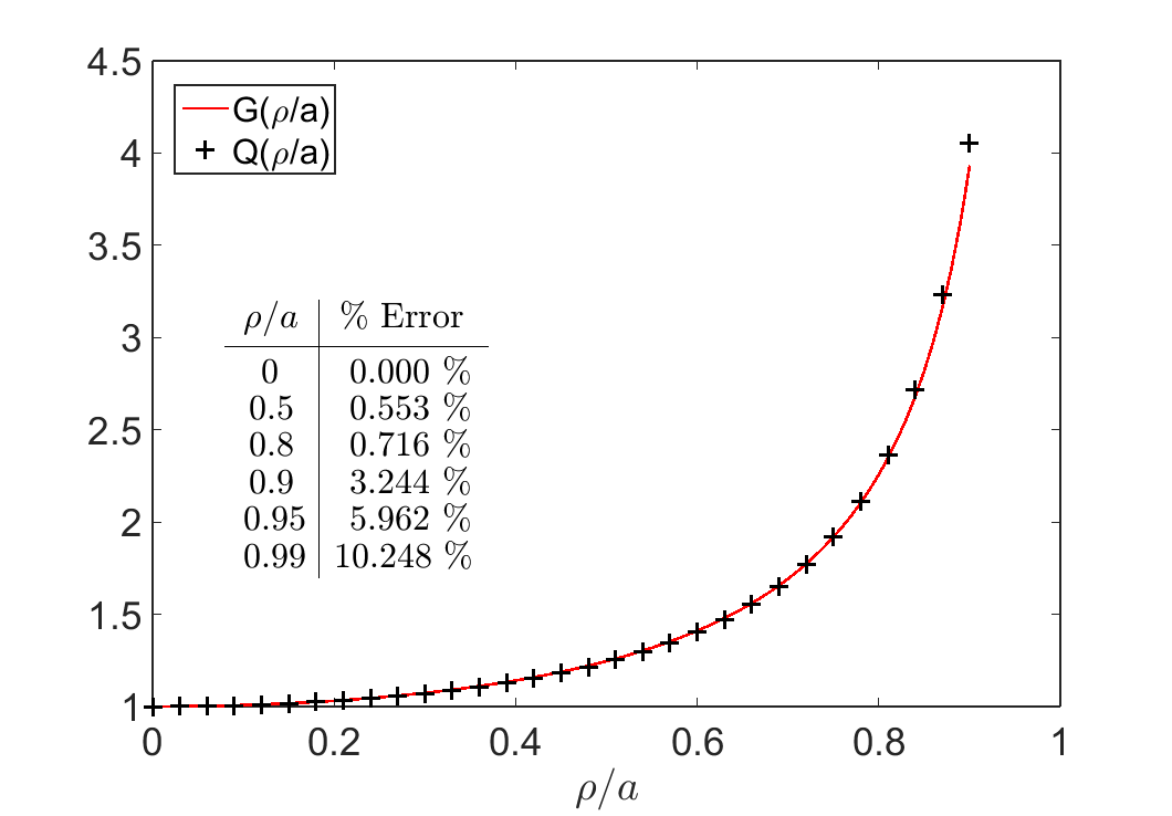
Figure 1:Comaparisson between and its approximation , for various values of . A
% error for selected values is provided.
For measurements inside the loop (), we would like to find an approximate solution for that does not contain the elliptic integral. At the center of the loop, , , Eq. (21) then simplifies to as expected. As , the static response approaches infinity. To preserve these properties, we suggest an empirical function as:
This approximation is accurate to within for values . For , the approximation increasingly overestimates (Fig. 1). Combining Eq. (21) with (22), we have the analytical formula for the vertical static response at any location for a loop located on the Earth surface (),
4.1.2Response Along the Transmitter’s Vertical Axis ()
When the transmitter loop is at height and the observation is along the vertical axis of the transmitter, i.e., at , the associated integral in Eq. (19) is reduced to an analytical expression by setting :
Substituting Eq. (24) into Eq. (17) leads to the vertical static response
where is the dipole moment of the transmitter.
4.2Radial Static Response for a Large Circular Transmitter Loop over a SP Half-space
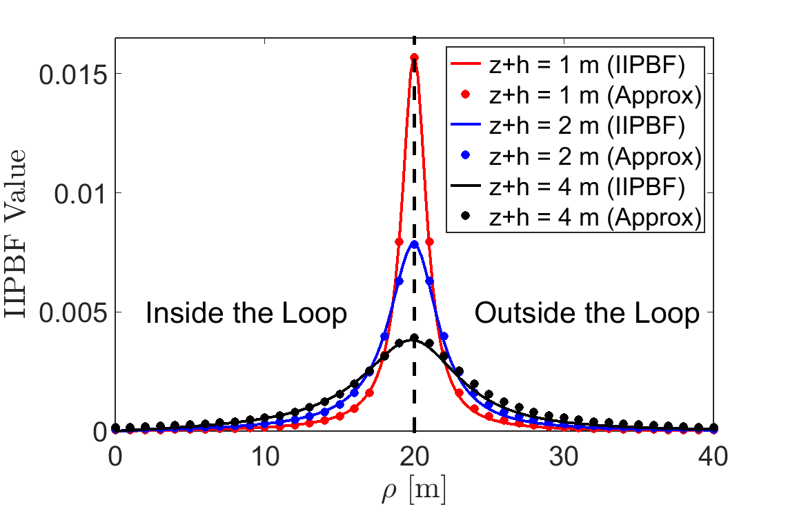
Figure 2:Comparison between computations of the Hankel transform using IIPBF adaptive quadrature and using the empirical expression from Eq. (27). Comparisons are done for various values of , using a loop radius of m.
Now we look at the radial static response from a circular transmitter loop over a SP half-space. According to Eq. (18), we require a solution to the integral:
Although analytic solutions for Eq. (26) exist Erdelyi et al., 1954, they are too complicated to develop straightforward relationships with respect to the transmitter loop radius and observation locations. However for the special cases considered below, we can have an approximate solution.
First, let us examine the behavior of Eq. (26). For , we used the IIPBF adaptive quadrature package Ratnanather et al., 2011 to evaluate the expression. Fig. 2 shows the results for several values of for a loop of radius m. We observed that for , the numerical solutions w.r.t behaved like a Cauchy distribution centered around . As is decreased over the accepted range, the distribution became narrow. Therefore invoking the probability density function for a Cauchy distribution, we proposed a heuristic approximation to Eq. (26) as:
where an empirical function for is given by:
One sees that in Fig. 2, the results from Eq. (27) match well with those using IIPBF adaptive quadrature. For , Eq. (26) approaches the Dirac delta function :
which can be shown with the weighted orthogonality property of the Hankel transform Li & Wong, 2008.
By combining Eqs. (27) and (18), the radial static response of the SP half-space for is approximated by
It should be noted that although Eq. (30) provides a reasonable approximation, it cannot be used to show that exactly. This property was obtained from Eq. (18) since .
5VRM Response from a Large Circular Transmitter Loop
Having obtained the approximations for the after-effect function and the analytical expressions for the static fields in several cases, we now look at the VRM response with Eqs. (15) and (16) over a SP half-space for .
5.1Vertical VRM Response from a Large Circular Transmitter Loop
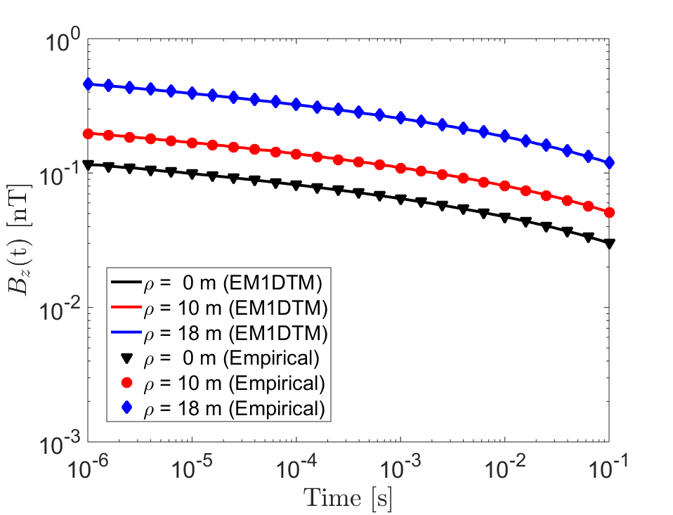
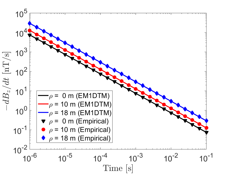
Figure 3:Vertical VRM response for a large circular loop of radius m on the Earth’s surface, at radial distance from the loop’s center, using properties , s and s. This plot compares expressions (31) and (32) to values obtained using the EM1DTM code. (a) . (b) .
5.1.1Large Circular Loop on the Earth’s Surface ()
With expressions (11), and (23), the vertical VRM response at any location at time is approximated according to Eq. (15)
Similarly after substitution of (13) and (23) into Eq. (16), we have
Both Eqs. (31) and (32) reveal that the vertical VRM response depends upon the ratio of . When an observation is made towards the center of a loop (say ), the response tends to be small and vary minimally with respect to . This agrees with the results obtained by others Buselli, 1982Barsukov & Fainberg, 2001. When an observation is made towards the edges of the loop, the VRM response can increase in magnitude rapidly as increases and . Fig. 3 shows the variation in the VRM response when for a loop of radius m. Meanwhile, the results of Eqs. (31) and (32) match well with those computed using the 1D numerical code-EM1DTM Farquharson (2006). In practice, measurements of or are not acquired directly on the Earth’s surface. Instead, data are typically collected at heights less than 1 m off the ground. Therefore for a near-surface survey with a sufficiently large loop, we should expect similar behaviour to the case above when .
5.1.2Response Along the Transmitter’s Vertical Axis ()
Using expressions (11), (15), and (25), we have the VRM response at time
Similarly, using expressions (13), (15), and (25), we obtain:
Eqs. (33) and (34) show that the VRM response becomes smaller in magnitude when the size of the loop or the total elevation of increases. This matches analytic results and field observations made by others Lee, 1984Buselli, 1982Barsukov & Fainberg, 2001. For a dipole source (), the magnitude of the VRM response is proportional to . For and , expressions (33) and (34) are equivalent to expressions (31) and (32) at . The VRM response observed for a loop of radius m is shown in Fig. 4 when . Again, both the analytical and numerical results agree well.
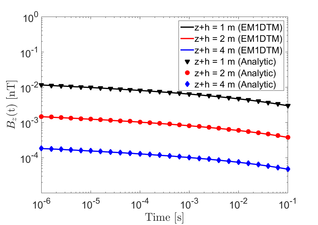
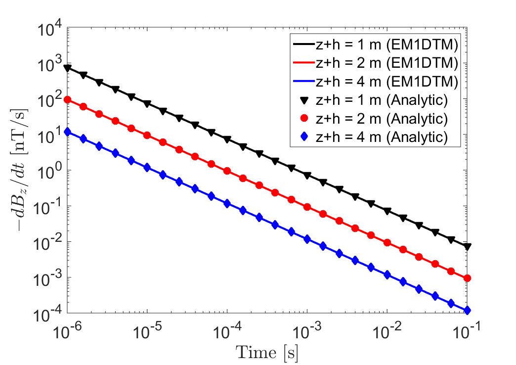
Figure 4:Vertical VRM response along the transmitter’s vertical axis of symmetry, using a radius of m. Responses were predicted for several values , using properties , s and s. Plots compare Eqs. (33) and (34) to values obtained using the EM1DTM code. (a) . (b) .
5.2Radial VRM Response from a Large Circular Transmitter Loop
Using Eqs. (11), (15), and (30), we express the radial VRM response for at time as
And using expressions (13), (15) and (30), we have
Eqs. (35) and (36) describe how the geometrical parameters can affect the response, although they are a bit more complicated than the expressions for the vertical component. Near the center of the loop, one can see that the radial component of the VRM response is small. As observations are made closer to the transmitter wire, the radial component of the VRM response increases significantly. Recall that given by Eq. (28) is a function of . Therefore, the effect of raising the receiver off the ground can be generated by raising the transmitter off the ground. This effect was observed during field observations for various SiroTEM configurations Buselli, 1982.
Figs. 5a and 5b shows the radial VRM response for given a loop of radius m and m. The analytical and the EM1DTM results overlap well. Similar to the vertical components, the VRM response of decays in , and decays in .

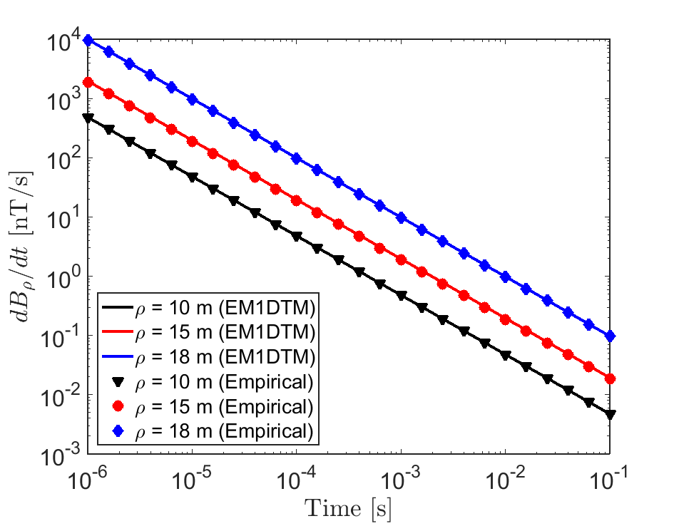
Figure 5:Comparison between EM1DTM and empirical functions (35) and (36) for the radial VRM response with a loop of radius m. The response was predicted for m using physical properties , s and s. (a) . (b) .
6Response over a Conductive and Magnetically Viscous Half-Space
The magnetic susceptibilities of lateritic soils are generally low () Dam et al., 2004Dam et al., 2005Druyts et al., 2009; as such, the magnetic properties of lateritic soils do not have a significant impact on the inductive response. Some studies showed that effects of conductivity may be neglected when considering the soil’s VRM response Billings et al., 2003Druyts et al., 2009Das, 2006. Some have suggested that the inductive and VRM responses from lateritic soils are approximately separable Pasion, 2007Buselli, 1982Das, 2006. In this section, we will test this assumption using the 1D numerical modeling code (EM1DTM) Farquharson, 2006 over a half-space model. Given that the inductive and VRM responses are separable, we present the critical time analysis by comparing the vertical inductive and VRM responses with respect to the loop’s radius and observation distances.
6.1Separation of Inducitve and VRM responses
Consider a conductive and magnetically viscous half-space with S/m, , , s and s. Fig. 6 shows the inductive, the VRM , and the total transient responses computed by EM1DTM for a loop of radius m on the surface. One sees that for the vertical and radial components after sufficient time, the observed response becomes dominated by the VRM response; whereas the early times appear to be dominated by the inductive response. The numerical results verify that the total response for a conductive and magnetically viscous Earth can be well approximated as the sum of the individual inductive and VRM responses and support the observations made by Dam et al., 2004Dam et al., 2005Druyts et al., 2009Billings et al., 2003Das, 2006Pasion, 2007Buselli, 1982. Overall, we found that for sufficiently small DC susceptibilities (), inductive and VRM responses could be predicted independently. For larger values of , magnetic properties can affect the inductive response. On the other hand, the VRM response was insensitive to changes to the half-space conductivity. Bear in mind that the value of has no effect on the VRM response as the contribution made by instantaneous magnetization during the off-time is zero.
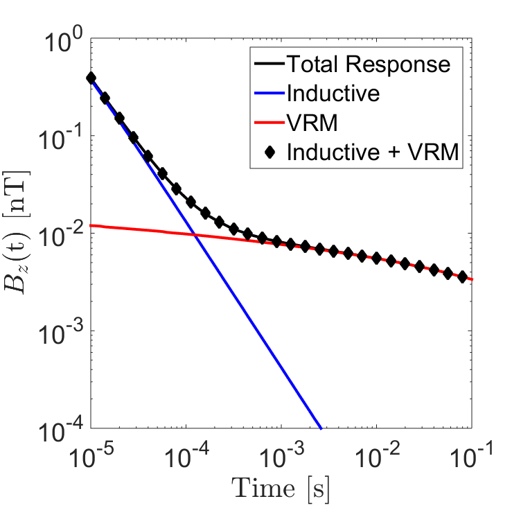
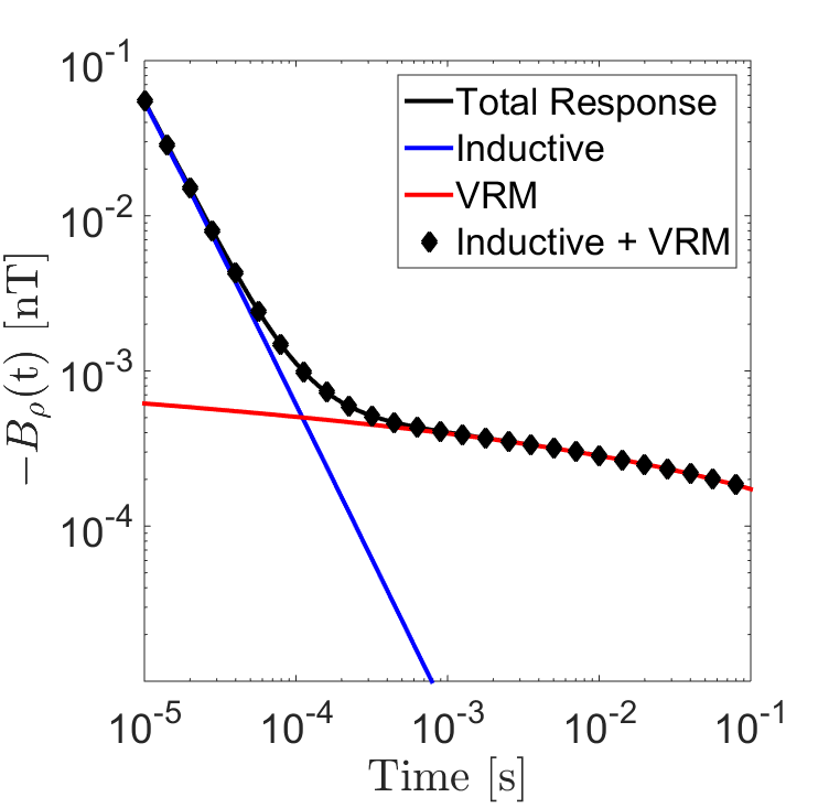
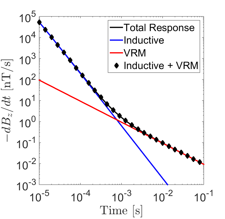
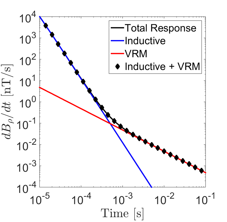
Figure 6:Additivity of the inductive and VRM responses for a loop of radius m at location () = (10 m, 1 m). The half-space was given physical properties: S/m, , , s and s. (a) . (b) . (c) . (d) .
6.2Estimating the Cross-Over Time of VRM Responses
Nabighian (1979) showed that for a step-off excitation, to first-order, the quasi-static inductive response within a large circular transmitter loop on the surface of a conductive half-space would approach the following expression asymptotically after sufficient time:
and that:
where is the loop’s radius, is the Earth’s conductivity and is the permeability of free space. Note that the inductive response and its derivative decay according to and respectively. Futhermore, the strength of the inductive response is proportional to .
As the inductive and VRM responses can be predicted independently, we want to inspect how both responses change over time. Refer to Fig. 6. We observe that the decay rate of the total response starts to change roughly at a time when the inductive curve intersects with the VRM curve. Thus by setting up the ratio between the vertical inductive response and the vertical VRM response with (11), (31) and (37)
and for the derivative with (13), (32) and (38)
we can estimate the time at which magnetic viscosity begins to dominate the vertical observed response. Such times are called the cross-over time. Let denote the cross-over time for , which solves in Eq. (39) . And let denote the cross-over time for , which solves in Eq. (40). For , the cross-over time is straightforward:
![Lower branch of the Lambert W function W[-1,x] for values -1/e \leq x \leq 0.](https://pub.curvenote.com/0199c741-d3c8-7ba1-b7a4-d38db53ff134/public/figW-5388dde493531f39b97a501352850a01.png)
Figure 7:Lower branch of the Lambert W function for values .
Eq. (41) states that by increasing the radius of a transmitter loop, the expected time at which becomes dominated by the VRM response is pushed to a later time. At the center of any loop, and . Because , as an observation moves towards the edge of the loop, we expect to decrease and thus the VRM response starts to dominate earlier.
For , the VRM response begins to dominate at time:
where is the lower branch of the Lambert W function Corless et al. (1996), is the Euler constant, and is given in (41). for values is shown in Fig. (7). Its derivation can be found in the Appendix.
Eq. (42) shows that is a monotonic increasing function with respect to . Although the dependence of on and is not straightforwardly represented in Eq. (42), we can qualitatively infer that TEM instruments which measure are much more affected by the VRM response than instruments which measure . It can be shown that for .
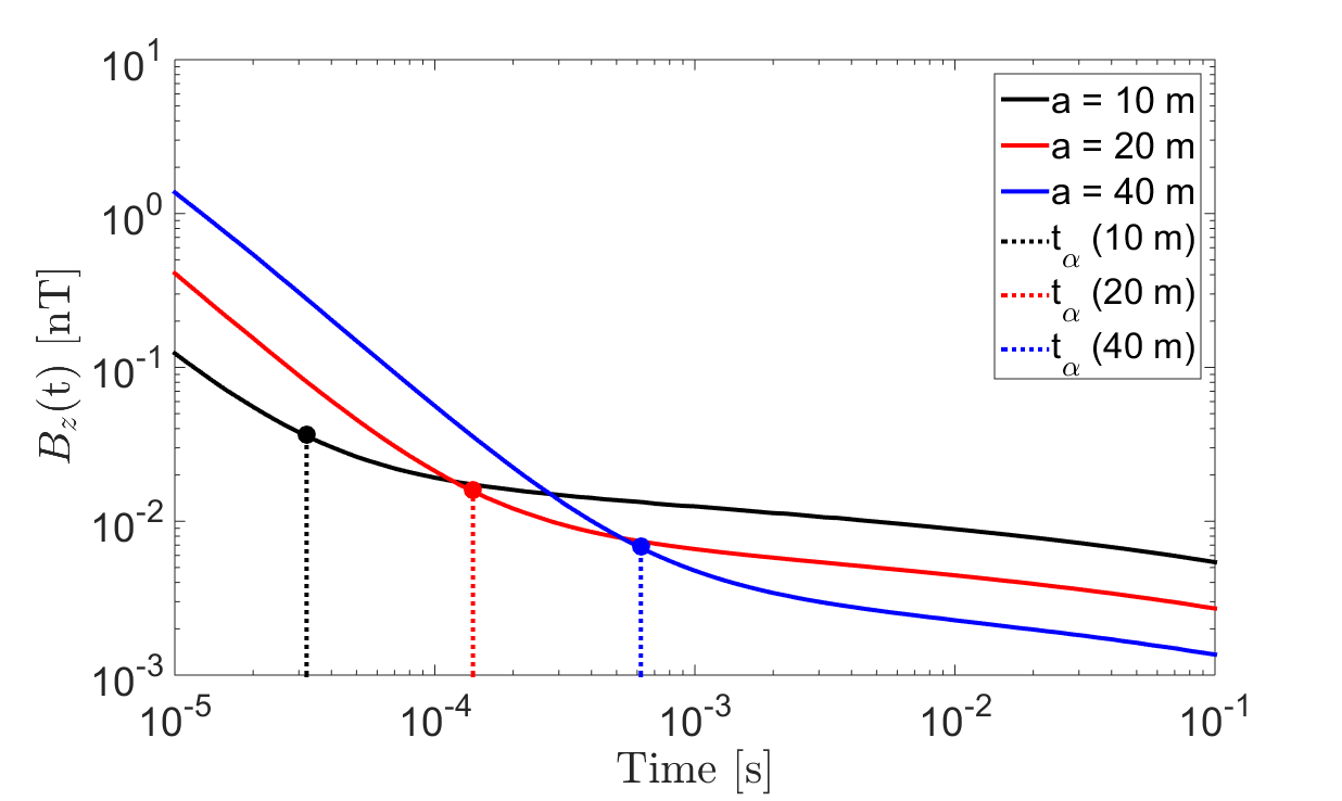

Figure 8:Vertical transient response at the center of a set of transmitter loops with varying radii, located on the Earth’s surface. EM1DTM was used to predict the responses for a half-space with physical properties: S/m, , s and s. (a) . (b) .
Fig. 8 shows the vertical transient responses calculated using the EM1DTM at the center of a transmitter loop when the radius m, 20 m, 40 m. and its corresponding value were calculated using Eqs. (11), (31), (37) and (42); and its corresponding value were calculated using Eqs. (13), (32), (38) and (41). It confirms that and increase with respect to , and that .
Consider the vertical transient responses in Fig. 9 at various radial locations for a transmitter loop with radius m. and its corresponding value were calculated using Eqs.(11), (31), (37) and (42); and its corresponding value were calculated using Eqs. (13), (32), (38) and (41). Similarly, we observe that and decrease with respect to , and that . Recall that in Eq. (22) increases as . Thus when observations are made closer to the transmitter loop, the VRM response will not only increase but will also dominate the total observed transient response at earlier times. This is consistent with the observation that magnetic viscosity is known to be most problematic near the transmitter wire Buselli (1982)Lee (1984)Barsukov & Fainberg (2001).
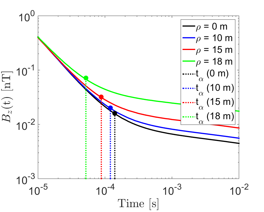
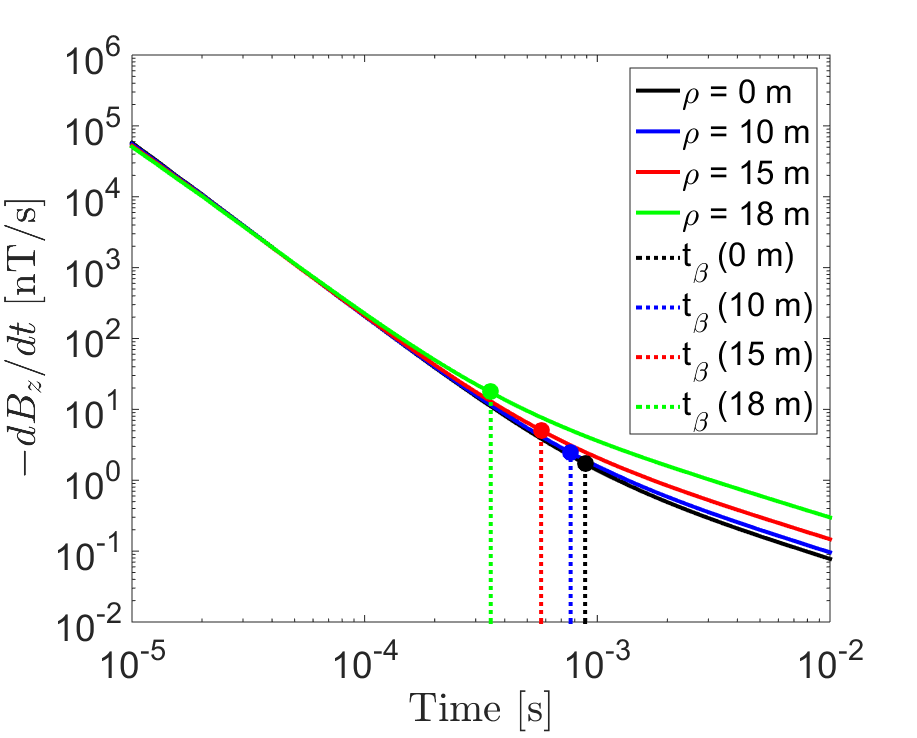
Figure 9:Vertical transient response at off-axis locations , for a loop of radius m, located on the Earth’s surface. EM1DTM was used to predict the responses for a half-space with physical properties: S/m, , s and s. (a) . (b) .
Figs. 8 and 9 demonstrate how Eqs. (41) and (42) can be used to estimate the cross-over times (dashed lines) at which and within the loop become dominated by the VRM response. The projection of and on the corresponding total response curve will appear earlier than the point of maximum curvature on each log-log plot (also see Fig. 6). Provided that a-priori information is supplied regarding the Earth’s physical properties, Eqs. (39) through (42) can provide some survey guides in practice. For example, Eqs. (39) and (40) can be used to help adjust a loop size that renders the VRM response negligible over a specified time range. With an estimated cross-over time, one can properly remove the VRM effects during the late-time response.
7Conclusion
In this paper, we have presented the analytical formulae for the transient VRM response generated by a large circular loop over a magnetically viscous half-space for a step-off excitation. Assuming that the soil’s magnetic viscosity is represented by a collection of non-interacting SP grains Néel, 1949 and that magnetic fields are governed by the magnetostatic law, we can express the VRM response and its derivatives as the product of a static field and an after-effect time function. We approximated the true after-effect function of the half-space by using a log-uniform distribution of time-relaxation constants to characterize the magnetic viscosity. As for the static fields, we derived the associated expressions by simplifying and approximating Hankel integrals for the vertical and radial field components. Analytic expressions were verified with the 1D forward modelling code Farquharson, 2006. Both analytical and numerical results showed excellent agreement for sufficiently small magnetic susceptibilities.
Our analytic expressions explicitly reveal how the VRM response depends upon geometric survey properties such as the transmitter loop’s size and the observation location within the loop. For vertical VRM responses measured near the surface, the ratio of plays a major role in controlling the magnitude. When , i.e., an observation is made towards the edge of the loop, VRM responses can increase significantly. Equivalently, strong VRM responses are expected for a smaller transmitter loops. For measurements along the axis of the loop, the vertical VRM response can be diminished by either increasing the sensor height or increasing the size of the loop. For radial VRM responses, our empirical approximation predicts that it is small near the center of the loop. As observations are made closer to the transmitter wire, the increased strength of radial VRM response can be damped by increasing the sensor height. Characteristics of the VRM response uncovered in the analytical expressions are consistent with other field observations and numerical modeling results Buselli, 1982Barsukov & Fainberg, 2001Billings et al., 2003Kozhevnikov & Antonov, 2008Pasion, 2007Zadorozhnaya et al., 2012.
Furthermore, we have suggested an estimate of the cross-over time from which the response might be divided into earlyinductive and late VRM stages. Increasing the size of a loop can push the cross-over time to a later time. On the other hand, a near loop-edge observation tends to have an early cross-over time. Also, we found that the VRM response impacts on the magnetic flux density at much earlier times than on its time derivative . Therefore in regions where lateritic soils are prominent, it may not be recommended to use TEM systems that only measure the magnetic flux density; which are potentially contaminated by the VRM signal across a larger number of time channels.
Overall, our analytical expressions can serve as a convenient design code for choosing an appropriate loop size and selecting an optimal range of observation times. This may prove beneficial when attempting to reduce the VRM response or pinpoint a certain time window where the VRM response can be properly removed.
Copyright © 2017 Cowan et al.
- SP
- super-paramagnetic
- TEM
- time-domain electromagnetic
- VRM
- viscous remanent magnetization
- Buselli, G. (1982). The effect of near-surface superparamagnetic material on electromagnetic measurements. Geophysics, 47(9), 1315–1324. 10.1190/1.1441392
- Barsukov, P., & Fainberg, E. (2001). Superparamagnetic effect over gold and nickel deposits. European Journal of Environmental and Engineering Geophysics, 72(6), 61–72. 10.3997/2214-4609.201406479
- Billings, S. D., Pasion, L. R., Oldenburg, D. W., & Foley, J. (2003). The influence of magnetic viscosity on electromagnetic sensors. EUDEM – SCOT2, Int. Conf. on Requirements and Technologies for the Detection,Removal and Neutralization of Landmines and UXO, Brussels. 10.1190/geo2017-0153.1
- Pasion, L. (2007). Inversion of time domain electromagnetic data for the detection of unexploded ordnance [Phdthesis]. http://adsabs.harvard.edu/abs/2007PhDT.......129P
- Zadorozhnaya, V. Y., Kozhevnikov, N. O., & Nyabeze, P. (2012). Superparamagnetic effect, effect provided by “red soil” in Southern Africa. EM Induction Workshop, 1–4. 10.1093/gji/ggv161
- Dabas, M., Jolivet, A., & Tabbagh, A. (1992). Magnetic-susceptibility and viscosity of soils in a weak time-varying field. Geophysical Journal International, 108(1), 101–109. 10.1111/j.1365-246X.1992.tb00841.x
- Néel, M. L. (1949). Théorie du traînage magnétique des ferromagnétiques en grains fins avec application aux terres cuites. Annales de Geophysique, 5, 99–136. 10.1017/CBO9781107415324.004
- Moskowitz, B. M. (1985). Magnetic viscosity, diffusion after-effect, and disaccommodation in natural and synthetic samples. Geophysical Journal International, 82(2), 143–161. 10.1111/j.1365-246X.1985.tb05133.x
- Butler, D. K. (2003). Implications of magnetic backgrounds for unexploded ordnance detection. Journal of Applied Geophysics, 54(1), 111–125. https://doi.org/10.1016/j.jappgeo.2003.08.022
- Pasion, L. R., Billings, S. D., & Oldenburg, D. W. (2002). Evaluating the effects of magnetic soils on TEM measurements for UXO detection. Society of Exploration Geophysicists Annual Meeting, 2–5. 10.1190/1.1816930
- Lee, T. (1984). The effect of a Superparamagnetic Layer. Geophysical Prospecting, 32(March 1983), 480–496. 10.1111/j.1365-2478.1984.tb01111.x
- Das, Y. (2006). Effects of soil electromagnetic properties on metal detectors. IEEE Transactions on Geoscience and Remote Sensing, 44(6), 1444–1453. 10.1109/TGRS.2006.870401
- Kozhevnikov, N. O., & Antonov, E. Y. (2008). The magnetic relaxation effect on TEM responses of a uniform earth. Russian Geology and Geophysics, 49(3), 197–205. 10.1016/j.rgg.2008.02.004
- Das, Y. (2004). A preliminary investigation of the effects of soil electromagnetic properties on metal detectors. Detection and Remediation Technologies for Mines and Minelike Targets IX, 5415(2), 677–690. 10.1117/12.541364
- Druyts, P., Das, Y., Craeye, C., & Acheroy, M. (2009). Modeling the response of electromagnetic induction sensors to inhomogeneous magnetic soils with arbitrary relief. IEEE Transactions on Geoscience and Remote Sensing, 47(8), 2627–2638. 10.1109/TGRS.2009.2013843
